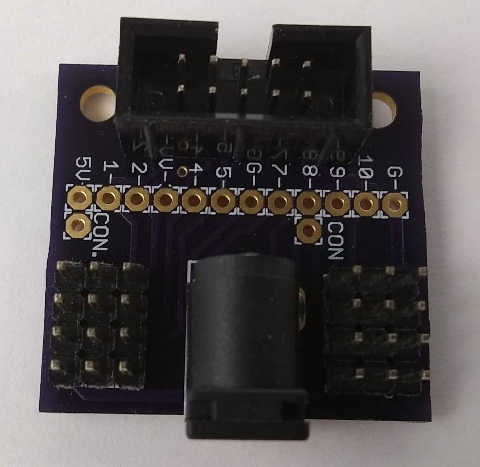
Servo Adapter Board
Design > Adapter Boards
The Servo Adapter Board
See photo gallery HERE.
The pins allong the edge of the board away from the barrel jack are ground. The middle pins are the positive power connected to the barrel jack, typically +5 volts, if attached. The pins closest to the barrel jack are the signal pins 1, 2, 4, 5, 7, 8, 9, 10. Pins 3 and 6 are power from the ribbon cable.
Attached at Position C
- The signal pin at position 1 connects to pin D5
- The signal pin at position 2 connects to pin D6
- The signal pin at position 4 connects to pin D4
- The signal pin at position 5 connects to pin D3
- The signal pin at position 7 connects to RESET, pin 3/28 on the Arduino Nano
- The signal pin at position 8 connects to pin D2
- The signal pin at position 9 connects to RX, pin 2 on the Arduino Nano
- The signal pin at position 10 connects to TX, pin 1 on the Arduino Nano
Attached at Position D
When attached to the Arduino Nano Adapter Board at position D the pins of the Servo Adapter Board are connected to digital pins as follows.
- The signal pin at position 1 connects to pin D9
- The signal pin at position 2 connects to pin D11
- The signal pin at position 4 connects to pin D13
- The signal pin at position 5 connects to pin D10
- The signal pin at position 7 connects to pin D8
- The signal pin at position 8 connects to pin D12
- The signal pin at position 9 connects to pin D7
- The signal pin at position 10 connects to pin D6


