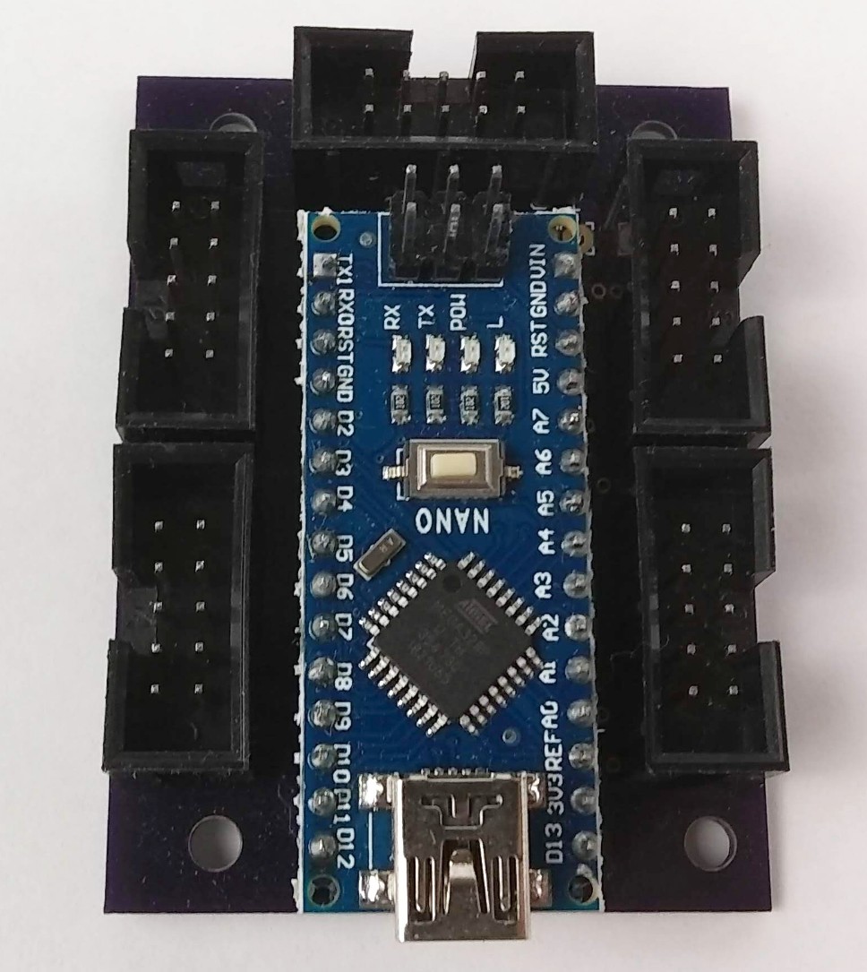
Arduino Nano Adapter Board
Design > Adapter Boards
Arduino Nano Breakout Board Design and Implementation
(Please note that what some people call a plug is what I call a socket, and vice versa!)
The Arduino Nano Breakout Board, ANBb, has no active components beside the Arduino itself. It simply connects 27 of the 30 Arduino Nano R3 pins to five standard 10-pin dual row PCB sockets having a total of 50 pins. A number of Arduino pins are routed to more than one socket pin. This redundancy creates flexibility so that the one board can be used in multiple configurations.
Of the five pins closest to the board edge the center pin in each case is pin 6 and ground. The five pins next to the board edge are the even number pins. Pin 1 is opposite pin 2, pin 3 is opposite pin 4, etc. Pin 3 in each case is +5 volts. This allows any one of the sockets to supply +5 to the Arduino. Also, ground and +5 volts are available where needed. The user is responsible to determine how to supply power to the system and to not overload the components.
The three Arduino Nano pins that are not brought out to one of the five sockets are Analog Reference (pin 17), 3.3 Volts Out (pin 16) and Vin (pin 30). Three pads on the PCB near Vin are connected to ground, +5 and Vin and may be used if needed. The socket shroud obscures the labels.
Looking at the board with the component side facing you and the Arduino Nano pin 1 (TX1) to your upper left, the socket on the end (top) of the board is Socket B. Counterclockwise from Socket B is Socket C and Socket D. Socket E is to the lower right. Socket A is in the upper right position between Socket E and Socket B.
See photo gallery HERE.

Arduino Nano Breakout Board (PDF)
The purpose and connections to each pin of each socket are noted in this PDF.
Arduino Adapter Cross Reference (PDF)

