April 22, 2020
Build Notes
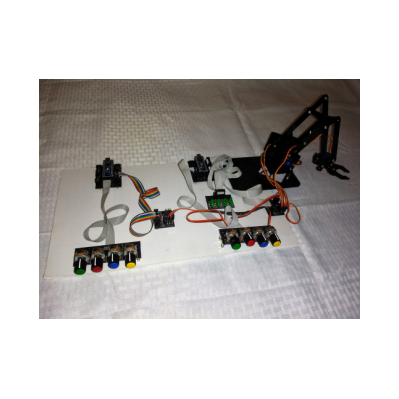
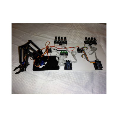
Legacy build showing development prototype with two connected Arduino Nanos.
April 2020 marked a transition in the development process.
The transition involved wiring changes and adding an additional serial I/O port to the Command module. The arrangement of the wiring had been stable for some time so it presents a possible starting point for others. One purpose of this page is to document this legacy hardware setup. During the transition I used this description of the wiring of the Servo node and the Command node in preparation for constructing and connecting the new base implementation that would include this new node. The second half of this page documents the new hardware arrangement with a few notes about the intent and design of the new node.
When this restructuring was completed the Command module had three serial I/O ports and began to resemble the future Routing module. With the final edits to this page a new period of software development was inaugurated using the new hardware arrangement.
The legacy Hardware was connected as follows.
- The PC ran the Arduino IDE. Two connections.
- One USB 2.0 port ran to the Command node.
- One USB 2.0 port ran to the Servo node.
- The Command node Nano Adapter Board.
- A Quad Pot Adapter board was attached at position B.
- A Servo Adapter Board was attached at position C.
- The Servo Adapter Board was not attached to power.
- A 47K resistor connected CON to +5 on this board.
- The Servo node Nano Adapter Board.
- A Quad Pot Adapter board was attached at position A.
- An 8 LED Board was attached at position D.
- A Servo Adapter Board was attached at position C powered by a 5 volt 1 amp USB power adapter.
- 4-servo Robot arm
- Pincer servo attached to Servo Adapter Board position 8
- Left/Right servo attached to Servo Adapter Board position 5
- Up/Down servo attached to Servo Adapter Board position 1
- In/Out servo attached to Servo Adapter Board position 4
- Serial Communications Interconnect cable
- Brown - Command-Servo Adapter Board ground to Servo-Servo Adapter Board ground signal
- Red (center wire) - Command-Servo Adapter Board signal pin 1 to Servo-Servo Adapter Board signal pin 2
- Orange - Command-Servo Adapter Board signal pin 4 to Servo-Servo Adapter Board signal pin 10
Hardware Notes.
- The purpose of the 47K resistor is so software can detect if servo power is being applied. Not only was this not implemented in this configuration but it is on the wrong board. This needs to be on the servo adapter board attached to the servo node.
- The serial communications interconnect cable has resistors in line with the red and orange connectors. The cable is wired brown female to brown female, red female to 1K resistor to red female and orange female to 1K resistor to orange female.
- The Servo node serial TX (i.e. TX1) is hard-wired to the RX of the command node. This means that everything transmitted to the console is also received by the command node. The servo module code never prints or writes to gtSerial! Arduino pin D12, the destination of gtSerial sends is connected to an LED.
Software
- Command node sketch
- SoftwareSerial gtSerial(4, 5); // RX is Arduino pin D4, TX is Arduino pin D5
- gtSerial.begin(57600); // software serial port
- Serial.begin(115200);
- Code
- Servo node sketch
- SoftwareSerial gtSerial(6, 12); // RX is Arduino pin D6, TX is Arduino pin D12 (see Hardware Notes above)
- gtSerial.begin(57600); // software serial port
- Serial.begin(57600);
- Code
This is the new arrangement connecting three Arduino Nanos.
The Nano furthest from the servo robot arm is the Command node. The center Nano is the TextSource node. The Nano closest to the robot arm is the Servo node. In this configuration the Command module has three serial I/O ports and begins to resemble the future Routing module. With the final edits to this page a new period of software development will be inaugurated using the new hardware arrangement.
Hardware of the new development configuration is connected as follows.
- Connections to the PC running the Arduino IDE.
- One USB 2.0 port runs to the Command node.
- One USB 2.0 port runs to the TextSource node.
- The Command node Nano Adapter Board.
- The Command node Nano is powered by the PC.
- A Quad Pot Adapter board is attached at position A. In the legacy configuration it was attached at position B.
- A Servo Adapter Board is attached at position D. In the legacy configuration it was attached at position C.
- The Servo Adapter Board is not attached to power.
- The TextSource node Nano Adapter Board.
- The Servo node Nano is powered by the PC.
- A Servo Adapter Board is attached at position D.
- The Servo Adapter Board is not attached to power.
- The Servo node Nano Adapter Board.
- The Servo node Nano is powered by a 5 volt 1 amp USB power adapter
- A Quad Pot Adapter board is attached at position A. This is the same as in the legacy configuration.
- An 8 LED Board is attached at position D. This is the same as in the legacy configuration.
- A Servo Adapter Board is attached at position C This is the same as in the legacy configuration.
- The Servo board is powered by a 5 volt 1 amp USB power adapter.
- A 47K resistor connects CON to +5 on this board
- 4-servo Robot arm
- Pincer servo attached to Servo Adapter Board position 8. This is the same as in the legacy configuration.
- Left/Right servo attached to Servo Adapter Board position 5. This is the same as in the legacy configuration.
- Up/Down servo attached to Servo Adapter Board position 1. This is the same as in the legacy configuration.
- In/Out servo attached to Servo Adapter Board position 4. This is the same as in the legacy configuration.
- Serial Communications Interconnect cable #1
- Brown - Command-Servo Adapter Board ground to Servo-Servo Adapter Board ground signal
- Red (center wire) - Command-Servo Adapter Board signal pin 7 (D8/TX) to Servo-Servo Adapter Board signal pin 2 (D6/RX)
- Orange - Command-Servo Adapter Board signal pin 8 (D12/RX) to Servo-Servo Adapter Board signal pin 10 (TX1/TX)
- Serial Communications Interconnect cable #2
- Blue- Command-Servo Adapter Board ground to TextSource-Servo Adapter Board ground signal
- Green (center wire) - Command-Servo Adapter Board signal pin 4 (D13/TX) to TextSource-Servo Adapter Board signal pin 1 (D9/RX)
- Yellow - Command-Servo Adapter Board signal pin 2 (see note) to TextSource-Servo Adapter Board signal pin 4 (D13/TX)
Hardware Notes.
- The Servo Adapter Board with the 47K resistor is attached to the Servo node so software can detect if servo power is being applied. However, CON is not attached to a digital input so cannot be sensed at this time.
- Serial Communications Interconnect cable #1 has resistors in line with the red and orange connectors. The cable is wired brown female to brown female, red female to 1K resistor to red female and orange female to 1K resistor to orange female.
- Serial Communications Interconnect cable #2 has resistors in line with the yellow and green connectors. The cable is wired purple female to purple female, yellow female to 1K resistor to yellow female and green female to 1K resistor to green female.
- Other developers have noted that SoftwareSerial is not reliable. Although it worked fine when one serial interface was instantiated it immediately failed for me when a second serial interface object was instantiated. Transmission from the command node to the text source node worked fine but the return side was unreliable. To solve this issue I modifed the code to use a bit bang algorithym. In the Command code serial characters come in on digital pin D11 which is pin 2 on the adapter board. This is why the constructor specifies D10 as RX which is pin 5 on the adapter board. This pin is not wired to anything. In the TextSource code serial characters are transmitted on digital pin D13 which is pin 4 on the adapter board. The constructor specifies D11 as TX which is pin 2 on the adapter board. This pin is not wired to anything.
- Serial Interconnects are not connected in the images above.
- The PC runs the Arduino IDE.
- Command node sketch
- SoftwareSerial gtSerial1(10, 13); // RX is Arduino pin D10, TX is Arduino pin D13
- SoftwareSerial gtSerial2(12, 8); // RX is Arduino pin D12, TX is Arduino pin D8
- Serial.begin(57600);
- gtSerial1.begin(57600); // software serial port
- gtSerial2.begin(57600); // software serial port
- Serial is the programming port
- gtSerial1 is the TextSource node
- gtSerial2 is the Servo node
- code (at the beginning of the development cycle)
- Servo node sketch
- SoftwareSerial gtSerial(6, 12); // RX is Arduino pin D6, TX is Arduino pin D12 (See note)
- Serial.begin(57600);
- gtSerial.begin(57600); // software serial port
- Serial is the programming port
- gtSerial is the Command node
- code (at the beginning of the development cycle)
- TextSource node sketch
- SoftwareSerial gtSerial(9, 11); // RX is Arduino pin D9, TX is Arduino pin D11
- Serial.begin(57600);
- gtSerial.begin(57600); // software serial port
- Serial is the programming port
- gtSerial is the Command node
- code (at the beginning of the development cycle)
Software Notes
- Note: The Servo node serial TX (i.e. TX1) is hard-wired to the RX of the command node. This means that everything transmitted to the console is also received by the command node. The servo module code never prints or writes to gtSerial! Arduino pin D12, the destination of gtSerial sends is connected to an LED.
- The posted code for the Command node and the TextSource node are from after I got the communications to work using bit-bang code on the Command side.
Version 0.1 of this page last edited: May 10, 2020.
Version 0.2 of this page last edited: May 17, 2020.
- Attached source code with debugged bit bang code.
- Other appropriate documentation.


